EEPROM INTERFACING WITH ARDUINO
In this project, we will show how to connect an 24LC256 EEPROM chip to an arduino micrcontroller. EEPROM is also very efficient in that individual bytes in a traditional EEPROM can be independently read, erased, and rewritten.
Synopsis

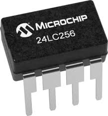
EEPROM stands for Electrically Erasable Programmanble Read-Only Memory. The Microchip 24LC256 eeprom is used in many projects for the storage of data when the microcontroller in use either doesn't have any eeprom memory or not enough. These useful eeproms use a simple I2C connection and are easy to setup and use.

In this project, we will show how to connect an 24LC256 EEPROM chip to an arduino micrcontroller. EEPROM is also very efficient in that individual bytes in a traditional EEPROM can be independently read, erased, and rewritten.

Description

The 24LC256, as the last 3 digits simply gives an additional 256 kilobits of EEPROM to an arduino micrcontroller. The EEPROM available on an arduino uno is 512 bytes of memory. So adding 24LC256 chip for EEPROM expansion is a significant one. It gives great EEPROM expansion. The 24LC256 EEPROM can operate on power anywhere from 2.5-5.5V.

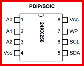
The 24LC256 is an 8-pin chip. The pinout of this chip is shown below.


First, to power the chip, we connect VCC, pin 8, to 5V. And we connect GND, pin 4, to power ground.

The address input pins, A0, A1, and A2, are for multiple device operation. If you are going to connect more than one 24xx256 EEPROM to a microcontroller, you will need to vary the addresses of each of the pins. So there are 3 address, which means there can be a total of 8 EEPROM devices connected together to a microcontroller (since 23= 8). If you have 8 EEPROMs connected together, each of them must have a unique address. The possible addresses are 000, 001, 010, 011, 100, 101, 110, and 111. The reason why each EEPROM must have a unique address is because there would be no other way for the microcontroller to address a specific one. The address is how you can differentiate between all the EEPROM chips. In this circuit, we simply connecting one EEPROM device to the microcontroller. Even with only being used, an address still must be used. We will ground all the address pins. This produces an address of 000. So this is what we will use for this circuit. But you can really make the address anything based on what address pins you pull HIGH or LOW. If you make A0 HIGH and A1 and A2 LOW, then this is an address of 001. If you make A1 and A2 HIGH and A2 LOW, then this is an address of 011. If you make all 3 address pins HIGH, this is an address of 111. It really doesn't matter when you have a single EEPROM. Just remember that when you connecting multiple devices, each one must be unique.

The WP pin, pin 7, is the Write-Protect pin. This pin can enable or disable the microcontroller writing data to the EEPROM chip depending on whether the pin is pulled HIGH Or LOW. If tied to HIGH or VCC, write operations are inhibited. Read operations, however, are not affected. If tied LOW or to VSS, write operations are enabled.

The SCL pin, pin 6, is the serial clock line. The 24LC256 operates off a clock signal. The clock is used to synchronize data transfer to and from the device between the arduino microcontroller and the EEPROM chip.

The SDA pin, pin 5, is the serial data pin. This is the pin that transfers data between the micrcontroller and the EEPROM chip. It's bidirectional.

The SDA pin, pin 5, is the serial data pin. This is the pin that transfers data between the micrcontroller and the EEPROM chip. It's bidirectional.

The module 24LC256 communicates Arduino with the microcontroller using a serial communication protocol called I2C. The I2C bus physically consists of 2 active wires. The wires, called SDA and SCL, are both bi-directional. SDA is the Serial Data line, and SCL is the Serial CLock line. Every device connected to the bus has its own unique device address, no matter whether it is an MCU or RTC module. Each of these chips can act as a receiver or transmitter, depending on the functionality. The interface to the Arduino is simple I2C with SDA and SCL pins are connected to the corresponding I2C pins of arduino. At the software side we are using an arduino library named “Wire” for I2C communication. This library allows you to communicate with I2C / TWI devices.

Proteus design for EEPROM interfacing with Arduino


Orcad design for EEPROM interfacing with Arduino


EEPROM interfacing with Arduino

/*  Name     : main.c
 *  Purpose  : Source code for External EEPROM Interfacing with Arduino.
 *  Author   : Gemicates
 *  Date     : 10-02-2018
 *  Website  : www.gemicates.org
 *  Revision : None
 */
#include <LiquidCrystal.h>
#include <Wire.h>

LiquidCrystal lcd(6, 7, 8, 9, 10, 11);                                                                     // initialize the LCD library with the numbers of the interface pins

void i2c_eeprom_write_byte( int deviceaddress, unsigned int eeaddress, byte data )
{
int rdata = data;
Wire.beginTransmission(deviceaddress);
Wire.write((int)(eeaddress >> 8));                                                                         // MSB
Wire.write((int)(eeaddress & 0xFF));                                                                       // LSB
Wire.write(rdata);
Wire.endTransmission();
}

void i2c_eeprom_write_page( int deviceaddress, unsigned int eeaddresspage, byte* data, byte length )
{
Wire.beginTransmission(deviceaddress);
Wire.write((int)(eeaddresspage >> 8));                                                                     // MSB
Wire.write((int)(eeaddresspage & 0xFF));                                                                   // LSB
byte c;
for ( c = 0; c < length; c++)
Wire.write(data[c]);
Wire.endTransmission();
}

byte i2c_eeprom_read_byte( int deviceaddress, unsigned int eeaddress )
{
byte rdata = 0xFF;
Wire.beginTransmission(deviceaddress);
Wire.write((int)(eeaddress >> 8));                                                                         // MSB
Wire.write((int)(eeaddress & 0xFF));                                                                       // LSB
Wire.endTransmission();
Wire.requestFrom(deviceaddress,1);
if (Wire.available()) rdata = Wire.read();
return rdata;
}

void i2c_eeprom_read_buffer( int deviceaddress, unsigned int eeaddress, byte *buffer, int length )
{
Wire.beginTransmission(deviceaddress);
Wire.write((int)(eeaddress >> 8));                                                                         // MSB
Wire.write((int)(eeaddress & 0xFF));                                                                       // LSB
Wire.endTransmission();
Wire.requestFrom(deviceaddress,length);
int c = 0;                                                                                                 // the variable which holds the data which is read from the eeprom
for ( c = 0; c < length; c++ )
if (Wire.available()) buffer[c] = Wire.read();
}

void setup()
{
char somedata[] = "GEMICATES";                                                                             // data to write
Wire.begin(); 
Serial.begin(9600);                                                                                        // initialize the serial port with baud rate 9600
i2c_eeprom_write_page(0x50, 0, (byte *)somedata, sizeof(somedata));                                        // write to EEPROM
delay(10);                                                                                                 //add a small delay
lcd.begin(16, 2);                                                                                          // set up the LCD's number of columns and rows: 
lcd.cursor();
lcd.print(somedata);                                                                                       // prints DATA which is stored before
}
void loop()
{
int addr=0;                                                                                                //first address
byte b = i2c_eeprom_read_byte(0x50, 0);                                                                    // access the first address from the memory
while (b!=0)
{

Serial.print((char)b);                                                                                     //print content to serial port
addr++;                                                                                                    //increase address
b = i2c_eeprom_read_byte(0x50, addr);                                                                      // access the first address from the memory
}
Serial.println();
delay(200);                                                                                                //add delay
}
Error message here!

Show Error message here!


Forgot your password?

Error message here!

Send OTP

Error message here!

Show Error message here!


Lost your password? Please enter your email address. You will receive a password you Need.

Send Error message here!


Back to log-in

Close